
Custom hydraulic rotary actuators for machine builders
Seven standard frame sizes from 180 Nm to 43,000 Nm — or we reverse-engineer any helical, vane or rack-and-pinion unit from your sample. One gated process, one fixed quote.
Four steps, one fixed quote
Inquiry & data
Send nameplate photo, old unit or drawing. Missing data? We measure the sample you ship.
Engineering
Reverse-engineering plus design review: torque, holding torque, bearing loads, duty cycle, mount type.
Prototype & test
Sample in 15–20 days door to door, with pressure, leak and function test report.
Production
Batch in 30–40 days. Serial-tracked, 12-month warranty, repeatable for spares.
Three parts, one motion
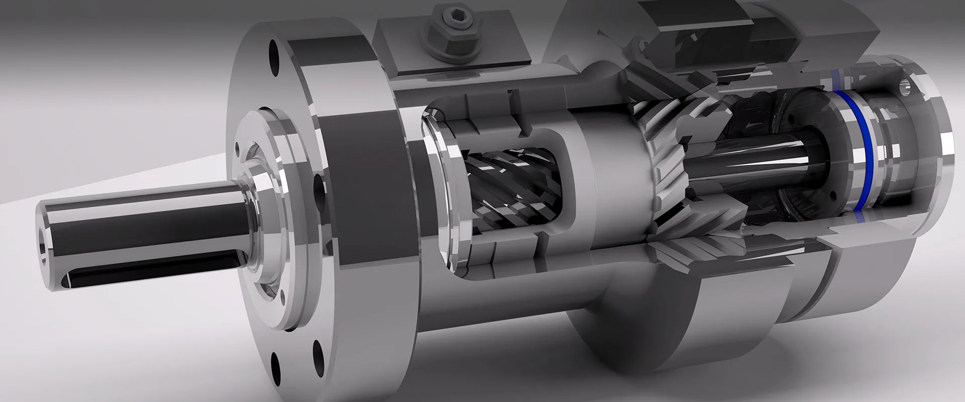
The helical rotary actuator replaces a rotary device, a mounting structure and a bearing with a single sealed unit: pressurise one port and the piston travels axially while its helical teeth force both piston and shaft to rotate. Pressurise the other port to return. No external brake is needed to hold position — internal leakage is effectively zero. The rotary actuator guide covers sizing, and how the design compares with vane and rack-and-pinion units.
Why it wins
- Holding torque 2–3× drive torque, without a brake
- Backdrives in overload — hydraulic fuse, protects the machine
- Rotation accuracy to ±10 arc-minutes; multi-turn to 1,500°
Counterbalance valve
- Factory-integrated dual counterbalance valve option
- Set 228 bar (L10/L20 size) or 250 bar (L30 size), pilot 3:1 / 2.5:1
- Aluminium or steel body; prevents rotation if a hose bursts
Read any HN code — example HN20-9-180-DZLCE
The code tells you everything: series, torque, angle, output, mounting, valve, seals. Use it to specify exactly what you need.
| Position | Code | Meaning |
|---|---|---|
| 1 | HN20 | Series: HN10 / HN20 / HN30 / HN40 / HN50 / HN60 / HN70 |
| 2 | 9 | Torque code = output torque Nm ÷ 100 (9 → 900 Nm @ 210 bar) |
| 3 | 180 | Rotation angle: 90 / 120 / 180 / 200 / 220 / 270 / 360; multi-turn custom to 1,500° |
| 4 | D | Output: D single flange · S double flange · J single spline · H double spline · K hollow shaft |
| 5 | Z | Mounting: Z foot · M saddle · F front flange · R rear flange · G rail (HN50: weld base) |
| 6 | L | Balance valve: L aluminium · G steel · W none · X custom |
| 7 | C | Seals: C ambient · D low-temperature · G high-temperature · Q custom |
| 8 | E | Motor / execution: E general · M custom |
DL-series codes follow the same logic with slightly different letters: output Q/S/Z/H; valve Y standard / W none / A aluminium / G steel / D custom; seals J ambient / D low-temp / H high-temp / G domestic.
What we can change
Performance
- Rotation 90° – 360° standard, multi-turn custom
- Torque 180 – 43,000 Nm @ 210 bar (HN ladder); beyond: to sample
- End-of-travel cushioning, angle adjustment ±4°
- Radial / axial load ratings per catalog size tables
Integration & environment
- Valve body steel or aluminium; spare ports on every unit
- Low-temp seal package for −40°C duty
- Ports ISO 11926 SAE / ISO 1179-1 BSPP "G"
- End-cap flange of straddle mounts carries ~10% of torque
Mounting & derating — read before you design
From the factory's engineering files, the three rules that decide actuator life:
| Rule | Detail |
|---|---|
| Cantilever vs straddle | Cantilever mounting (load bolted to the torque flange, supported at one end only) is not recommended for safety-critical duty such as aerial work platforms. Use straddle mounting — load supported at both shaft ends, foot-mounted; the end-cover flange additionally transmits ~10% of total torque. |
| Pressure–torque linearity | Output torque and holding torque are linear with system pressure — size for your real working pressure, not for 210 bar. |
| Bending-moment derate | Applied bending moment reduces available output torque — up to ~15% at rated moment. Keep the load close to the mounting face. |
Custom builds — common questions
How long does a custom rotary actuator take?
A sample takes 15–20 days door to door and ships with a pressure, leak and function test report. Production batches follow in 30–40 days — serial-tracked, with a 12-month warranty, and repeatable for spares.
What do you need from me for a quote?
The starred fields in the inquiry form below are enough for a first budgetary quote within 24 hours. A nameplate photo, the old unit or a drawing lets us engineer it exactly — if data is missing, we measure the sample you ship.
Can you copy a vane or rack-and-pinion actuator?
Yes. Besides the seven standard HN frame sizes (180–43,000 Nm), we reverse-engineer helical, vane and rack-and-pinion units from your sample.
What rotation angles can you build?
90°, 120°, 180°, 200°, 220°, 270° and 360° as standard, and multi-turn custom builds up to 1,500°. End-of-travel cushioning and ±4° angle adjustment are available.
Do I need a counterbalance valve?
Specify one wherever the load must not move if a hose bursts: the factory-integrated dual counterbalance valve stops the actuator rotating in that case. It is set to 228 bar on L10/L20 sizes and 250 bar on L30 sizes, pilot 3:1 / 2.5:1, in an aluminium or steel body — and every series is available with or without it.
Can HN actuators work in extreme temperatures?
Yes. A low-temperature seal package covers −40 °C duty, and high-temperature and custom seal packages are available — seal codes D, G and Q in the model code.
What does a model code like HN20-9-180-DZLCE mean?
HN20 series; torque code 9 = 900 Nm at 210 bar; 180° rotation; D single-flange output; Z foot mounting; L aluminium balance valve; C ambient seals; E general execution. The decoder table lists every option.
Custom inquiry
Fields marked * are enough for a first budgetary quote within 24 hours. Attachments: reply to our confirmation email with photos or drawings.