
Helical hydraulic rotary actuators — how they work and how to size one
A helical hydraulic rotary actuator turns the straight-line push of a piston into high-torque rotation through helical splines, and holds its position without a brake. This guide explains the mechanism, compares it with vane and rack-and-pinion designs, and walks through sizing for torque, pressure, angle and mounting.
What is a helical hydraulic rotary actuator?
A helical hydraulic rotary actuator is a sealed unit that delivers limited-angle rotation — 90° to 360° as standard — at high torque. It has three working parts: a housing with a fixed ring gear, an annular piston and the output shaft, connected by helical splines so that axial piston travel becomes shaft rotation.
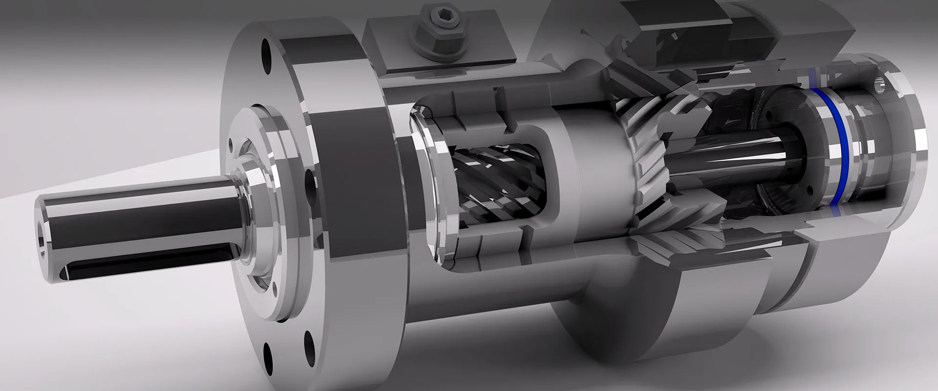
How the motion is produced
- Oil enters one port and pushes the piston along the bore.
- Splines on the piston's outside diameter mesh with the ring gear fixed in the housing, so the piston turns as it travels.
- Splines on its inside diameter drive the output shaft, which turns further still — the two rotations add up to the output angle.
- Pressurise the other port and the piston returns, rotating the shaft back.
Why machine designers choose it
- Holds position with its ports closed — internal leakage is effectively zero, so no external brake is needed
- Holding torque about 2 to 4 times drive torque
- One sealed unit replaces a rotary device, a mounting structure and a bearing
- The sliding spline absorbs shock, and the unit backdrives in overload — a hydraulic fuse
- Rotation accuracy to ±10 arc-minutes; multi-turn custom builds to 1,500°
Helical vs vane vs rack-and-pinion rotary actuators
All three turn hydraulic pressure into rotation. They differ in how well they hold position, how much external load they carry and how much space they take.
| Helical (sliding spline) | Vane | Rack and pinion | |
|---|---|---|---|
| Rotation | 90°–360° standard; multi-turn custom builds to 1,500° | Up to about 280° with a single vane, about 100° with a double vane | Set by rack length; 360° and more is common |
| Holding position | Effectively zero internal leakage — holds a load without a brake | Leakage past the vane seals; holding a load usually needs an external brake or valve | Holds well with good piston seals; gear backlash adds play |
| External loads | Large internal bearings carry radial, axial and bending loads — the load mounts directly | Limited; heavy loads need separate bearings | Heavy-duty units carry large bearings, at the cost of size |
| Envelope | Compact cylinder, in line with the shaft | Short and compact | Long — the piston and rack run across the pinion |
| Typical use | Mobile machinery: booms, attachments, aerial work platforms, drilling rigs, marine deck gear | Light indexing and valve actuation | Industrial indexing and valve actuation at very high torque |
Vane and rack-and-pinion characteristics are typical industry values, not HN data. Have a vane or rack-and-pinion unit to replace? We reverse-engineer either from a sample — start a custom inquiry.
How to size a rotary actuator
Four checks decide the size. Catalog torque is quoted at 210 bar, and both drive and holding torque scale linearly with pressure — so size for the pressure your circuit really runs at, not for 210 bar.
Torque at your pressure
Required torque × 210 ÷ your working pressure gives the 210-bar rating you need. Choose the next size up.
Holding torque
Check the static load the actuator must hold with its ports closed — holding torque is about 2 to 4 times drive torque.
Bending moment
An overhung load reduces the available torque — by up to about 15% at rated moment. Keep the load close to the mounting face.
Angle, mounting, valve, seals
Pick the rotation angle, straddle-mount safety-critical loads, and specify a counterbalance valve and low-temperature seals where the duty needs them.
A boom needs 6,000 Nm and the circuit runs at 180 bar. 6,000 × 210 ÷ 180 = 7,000 Nm needed at 210 bar, so the next HN30 size up is HN30-73 — rated 7,300 Nm at 210 bar, about 6,260 Nm at 180 bar. If the load is overhung, apply the bending-moment derate before you settle on the size — or send us the duty and we size it for you.
Cantilever vs straddle mounting
How the load is supported is one of the three rules that decide actuator life — the other two are sizing for your real working pressure and derating for bending moment.
Straddle mounting
The load is supported at both shaft ends and the actuator is foot-mounted. The end-cover flange also transmits about 10% of the total torque.
- The rule for safety-critical duty such as aerial work platforms
- Required for drum cutters and milling attachments, which need stiff, shock-tolerant rotation
Cantilever mounting
The load is bolted to the torque flange and supported at one end only.
- Not recommended for safety-critical duty — never cantilever a man-lifting boom
- Keep the load close to the mounting face to limit the bending-moment derate
Counterbalance valves, ports, seals and outputs
| Option | What to specify |
|---|---|
| Counterbalance valve | Optional on every series, factory-integrated; stops rotation if a hose bursts. Set 228 bar on L10/L20 sizes and 250 bar on L30 sizes, pilot 3:1 / 2.5:1, aluminium or steel body. |
| Ports | ISO 11926 SAE or ISO 1179-1 BSPP "G", with spare ports on every unit. |
| Seals | Ambient, low-temperature (−40 °C duty), high-temperature or custom packages. |
| Output | Single or double flange, single or double spline, or hollow shaft. |
| Mounting | Foot, saddle, front or rear flange, or rail — and a weld base for excavator tilt hitches. |
| Angle and stops | 90°–360° standard, multi-turn to 1,500°; end-of-travel cushioning; ±4° angle adjustment. |
Every option has a letter in the HN model code — see the model code decoder.
Rotary actuator terms
- Drive torque
- The torque an actuator delivers while it rotates, quoted at a stated pressure — 210 bar (21 MPa) for every HN figure on this site.
- Holding torque
- The torque an actuator resists with both ports closed, without rotating. On a helical actuator it is about 2 to 4 times the drive torque.
- Rotation angle
- The total travel from end stop to end stop — 90° to 360° as standard — set by the piston stroke and the lead of the helical splines.
- Torque ladder
- The sequence of standard sizes in a series. HN10, HN20 and HN30 follow the same ladder as Helac L10, L20 and L30.
- Backdriving
- Rotation forced by an external load. A helical actuator backdrives when overloaded, acting as a hydraulic fuse that protects the machine.
- Counterbalance valve
- A pilot-operated valve on each port that holds the actuator and controls an overrunning load; it stops rotation if a hose bursts.
- Straddle mounting
- The load is supported at both shaft ends and the actuator is foot-mounted — the rule for safety-critical duty such as aerial work platforms.
- Cantilever mounting
- The load is bolted to the torque flange and supported at one end only — compact, but not recommended for safety-critical duty.
- BSPP and SAE ports
- The two port thread standards used on HN units: ISO 1179-1 BSPP “G” parallel threads and ISO 11926 SAE straight threads with an O-ring seal.
Rotary actuator questions
What is the difference between drive torque and holding torque?
Drive torque is what the actuator delivers while it rotates; holding torque is what it resists with its ports closed. On a helical actuator, holding torque is about 2 to 4 times the drive torque — check the figure for your size in the interchange table.
Does a helical rotary actuator need a brake?
No. Internal leakage is effectively zero, so it holds position with its ports closed. Add a counterbalance valve if the load must not move when a hose fails.
How far can a helical rotary actuator rotate?
90° to 360° as standard. Multi-turn custom builds reach 1,500°.
How do I convert catalog torque to my working pressure?
Torque is linear with pressure: torque at your pressure = torque at 210 bar × (your pressure ÷ 210). An HN30-73 rated 7,300 Nm at 210 bar delivers about 6,260 Nm at 180 bar.
Why use a helical actuator for shock loads?
The sliding spline absorbs shock better than a gear rack, and the actuator backdrives when it is overloaded — a hydraulic fuse that protects the machine instead of breaking.
Can a vane or rack-and-pinion actuator be replaced with a helical one?
Often, yes. Send the unit or its nameplate: we reverse-engineer helical, vane and rack-and-pinion actuators from a sample and quote a replacement for your mounting and duty.